
11th Gen FMIC: End Tank Flow Optimization - Design Blog Pt. 2
Welcome to part 2 of our design blog series for our 11th generation Honda Civic Front Mount Intercooler Kit upgrade.
In part 1, we gave you the 101 on your OEM system. We talked in brief about the various parts of the system. In these next couple of blogs we will break down these key areas of the system in greater detail to explain to you how they work and how 27WON is going to make them better, or should I say REDEFINE them.
In a modern turbocharged car, one could make the case that, after the turbocharger itself, the intercooler core is the next most important component in the intake tract. It has the vital role of making the air as cool as possible before it gets to the engine to make us loads of horsepower. Both the CFM (amount of air moved) and the temperature of the air are key factors to consider.
Now when most aftermarket companies design an aftermarket upgraded intercooler for the Honda Civic they put all the emphasis on the core itself. They seem to take the bigger is a better approach and jam the largest core behind the bumper they can fit. While bigger is better is part of the equation, it is not the whole picture. We will dive into core selection in a later blog but for this blog, we want to take a close look into the things that are attached to each end of the intercooler core – the end tanks.
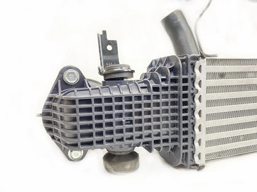
OEM Intercooler for the 2022+ Honda Civic
We have learned during our research and development of the 10th generation Honda Civic FMIC that the OEM intercooler tends to produce a very biased velocity profile. Air efficiently flows through only a part of the core due to the sharp bends in the OEM piping. For our design of this next generation, FMIC even more powerful CFD simulations were performed.
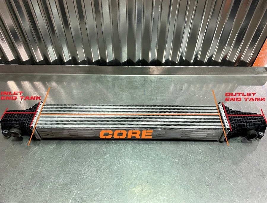
Front Mount Intercooler Core and End Tank Breakdown
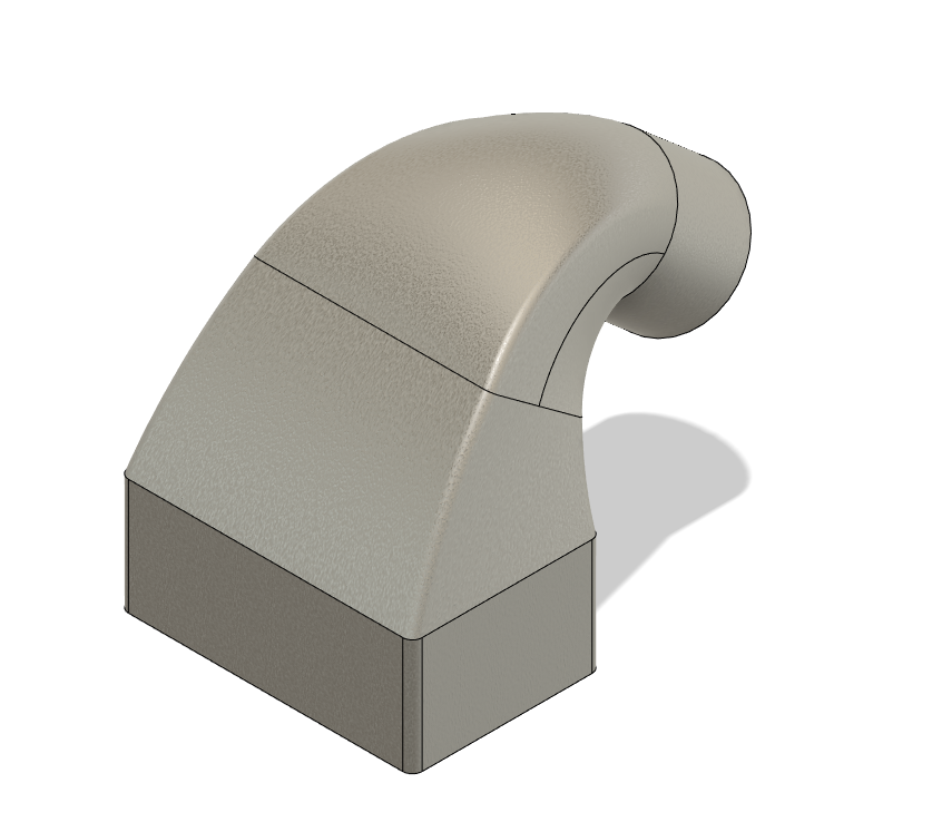
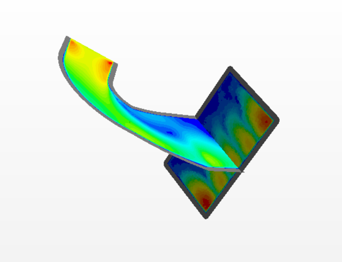
To get us started we made a rough design that is close to the OEM design. We didn’t want to spend the time to reproduce the OE design exactly. This simpler version illustrates the point. The OEM end tank is a small end tank with a smooth internal surface and a sharp 90◦ turn. Once we had this rough design, computer simulations were performed to see how well it behaves. The flow simulations tell us that this design is not ideal for making lots of power. The image shown below demonstrates that the airflow has a few different layers with different velocity profiles. Notice the different colors in the picture? Will explain those in more detail soon.
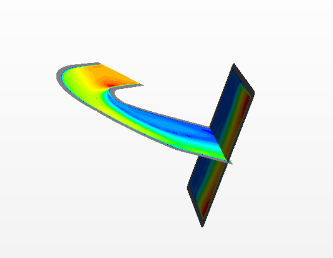
In layman terms, the boosted air leaving your turbocharger goes into the end tank where it hugs the outside of the tank before going into the core. Despite having a core “x” thick, only the outer ⅓ of it (green colors) does most of the work. That’s not optimal! Why only use ⅓ of something? Let's fix that.
To help make sure the hot air uses all of the core we introduced airfoils into the end tank. This helps redirect airflow. To find the best pitch and size of airfoil multiple simulations were performed.
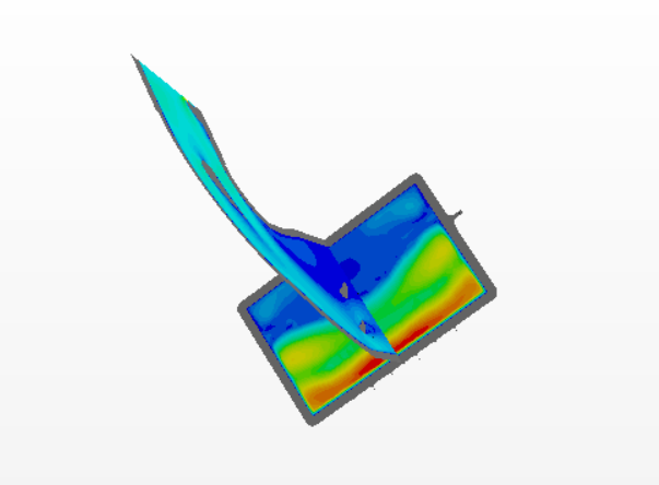
First, let’s make sure you can understand these images. In these images, you can see warm and cold colors. The warmer the colors, like orange and yellow for instance, show where the majority of the air is flowing. The colder colors like green and blue indicate slower and less air.
Now, compare the first image with no airfoils in the end tank (the mock OE design) to the others. On the ‘OE’ design you see the airflow is moving super fast on the front side of the intercooler core and much slower at the backside of it. This causes the backside of the core to not reject as much heat as the front and hence you are only really using part of the core efficiently.
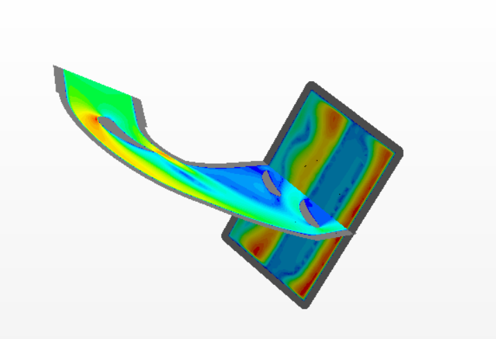
While you see a few iterations of our designs above, we’ll next look closer at the best one we show you now. We added airfoils to all these other designs. The location and pitch of these airfoils were optimized through lots of flow simulations. Thus our newly designed 11th gen Civic end tanks have optimally placed airfoils to get more even flow through the core. Check out the difference in flow as represented by the new color profile. The improvement of the air mixture at the inlet side is clearly observed through the use of the airfoils. More free power is made just by bringing in a little bit of fluid dynamics.

27WON Optimized Intercooler End Tanks
In order to incorporate these airfoils into our design, we will be utilizing cast end tanks. Now you might be wondering - why not billet? Well, the main reason is we don’t wish to compromise on this design by taking shortcuts. There is a reason why you won’t see airfoils in a billet end tank. That is because it is nearly impossible to machine on a CNC. This type of complexity requires casting technology. You’ll notice the 11th gen is similar in many ways to the 10th gen. It would be tempting to use components from the 10th gen to get an FMIC to market quickly, but this will result in a sub-optimal FMIC. True innovation and quality on a system this complex takes time.
The new airfoil design is just one of the many new tricks up our sleeves for our FE1 and FL1 front mount intercooler kit. Be sure and stick around for part 3 as we dive into my personal favorite new feature of the 27WON intercooler kit, talk more science, and wrap up end tank design.
Till next time, I dare you to REDEFINE the Aftermarket.
-Vincent