
27WON Honda Civic Intake Design Breakdown
As you’ve seen in recent post in the blog and social media, we are diligently working on a performance intake system for the 2016+ Honda Civic. Just a few weeks ago we dove into the OE intake system to better understand Honda’s design goals and methods. Now we are going to dive into the 27WON Performance Cold Air Intake System.
Like the 27WON Performance Exhaust for the Hatchback Sport, we approached the design with four critical goals in mind: Installation, Fitment, Style, and Performance.
Like I said, these are all critical aspects to a performance automotive part, but as we are still in the prototyping phase, I’d like to focus on the design and proof of concept.
First: Define the Goals.
We knew the intake system needed to help the engine make more power, but how? More air and denser air are the best and simplest solutions. We went to the drawing board (actually the scanning arm) to get creative. Using a CMM we were able to define the OE mounting points and the constraints in the engine bay that we would have to work around. With this information we could create a CAD modeled prototype then 3D print and test fit to begin the iterative process.
To no surprise, the first design was drastically different than the near-final design you’ve seen some CAD renderings of.

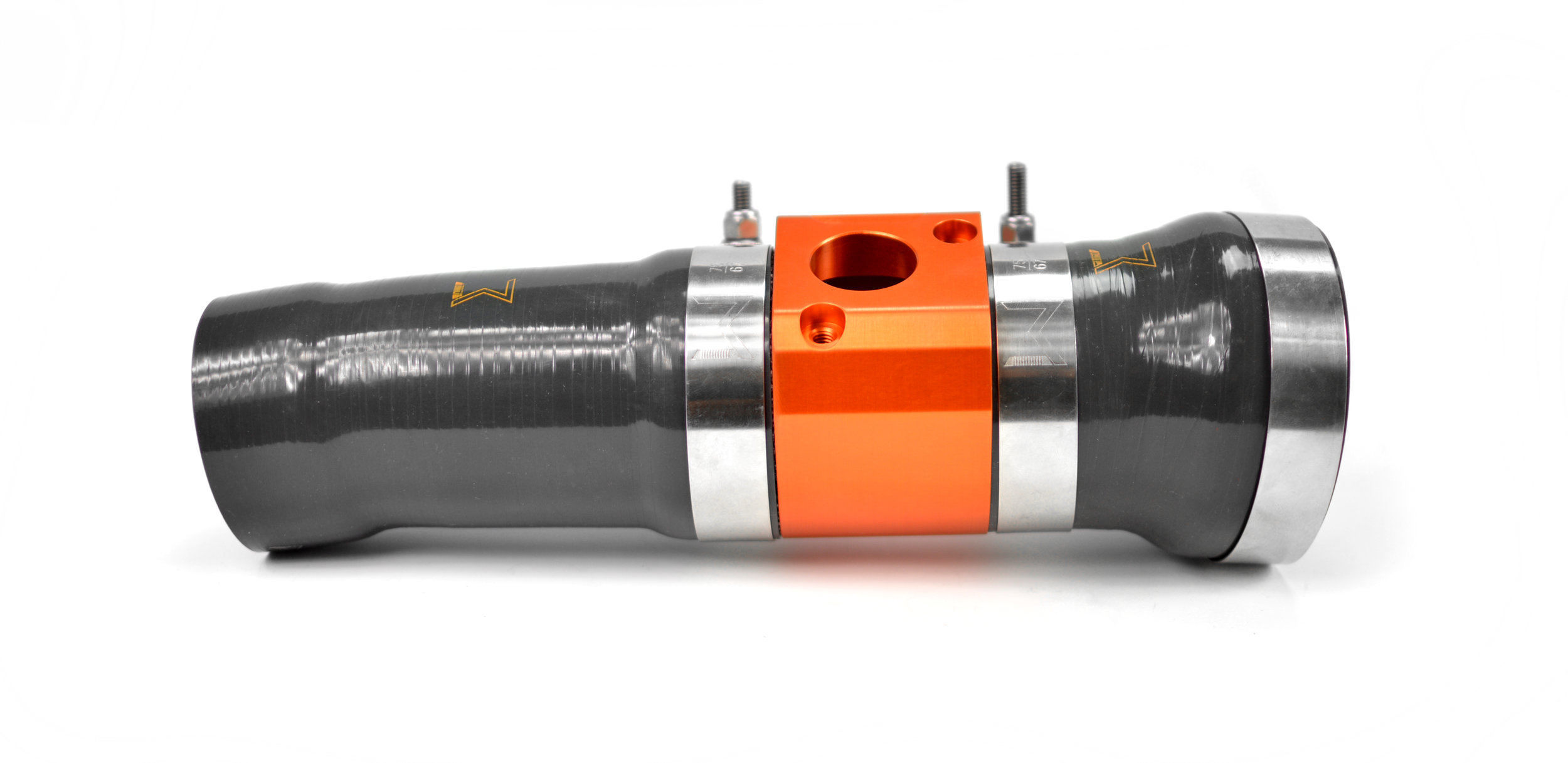
Once we were satisfied with the design of the airbox, we began to tackle the design of the MAF housing and silicone couplers. The couplers may appear to be a simple tube, but like Mamma always said “it’s what’s on the inside that is important”. Airflow prefers a smooth path to pass through, not one with edges and sharp bends, as they can disrupt the airflow causing turbulence which is essentially an inefficiency of the system. We won’t accept that in a 27WON Performance design so we took the silicone, billet MAF hosing and airbox to the next level in an integrated system.

The internal surface of the entire system is smooth; no edges, no sharp bends, no causes for turbulence.
This is the key to the design of the 27WON silicone couplers; a simple detail that can be overlooked, but can make a huge difference in the overall performance of the system.
So what else is going on in this system? Along with the silicone is a billet aluminum MAF housing with an anodized orange finish that will really make a statement in your engine bay. Pair this with a high-flow non-oiled air filter and you have yourself a complete high flowing intake system.
Now that covers the flow aspect of the intake system, but what about the cooler denser air? We’ll go back to the airbox for that; which you were probably wondering about anyway, due to its unique design.

Where to start… there’s a lot going on with the 27WON Performance Cold Airbox: how about the most obvious difference with the design, the large opening at the bottom.
This opening is the real key to the cooler denser air we want to get to the engine. This lower inlet is positioned to take in air from the inner fender just behind the front bumper skin. This area is not really a part of the engine bay and therefore does not get saturated with engine waste heat from the radiator, engine block, exhaust and various other components. However, there is a concern with sourcing air from the lower inner fender especially if the filter was directly located in this spot… debris and water. Being lower to the ground and having more open access to the road surface increases the chance for hydro-locking the engine. We had to avoid that risk and therefore located the air filter high up in the airbox.

Next, looking at the top of the box, you see a translucent cover along with some precisely located holes in the cover and front of the airbox.
These holes align with the OE positioning and provide a secondary air entrance in the case that the lower opening became fully submerged (now let’s be real, if your car is in water that deep you probably have other issues, but a hydro-locked engine won’t be one of them). We haven’t confirmed it yet, but the secondary openings in the top of the airbox may even help with allowing hot air to rise out of the airbox instead being trapped inside, which could happen while sitting in traffic.
Now the real question… does it work?
YUP, and quite well.
Before and after dyno testing shows a considerable drop in intake air temperatures measured at the MAF sensor. We saw a drop in IAT of approximately 30 degrees F. That’s astounding! As of right now we only have on-dyno testing performed, but we feel pretty confident that highway testing will show impressive drops in IAT as well.
Now, I’m going to stop at this point here. (Right with when things were getting good, I know.)
Next time, we will dig into the IATs some more and start talking about power. Thanks for tuning-in with 27Won Performance.
I dare YOU to Redefine The Aftermarket
-Barett @ 27WON Performance