
10gen Honda Civic Turbocharger Breakdown Pt.1
It’s amazing to see how fast the CivicX platform has grown in the aftermarket community for only being available around two years. The platform has a couple robust tuning solutions, a handful of excellent performance parts companies rapidly developing new components, and a community that is more than eager to continue growing. It really is an exciting time for the Honda brand.
We point this out because in just two short years there is already talk (even more so recently) about new performance turbochargers for the Civic 1.5L turbo engine, so we figured we give you something BIG to talk about
Before we dig into the design details of the our upcoming 27WON Performance W1 Turbocharger, we wanted to take the opportunity to educate you and help you better understand what a turbocharger is, its function, and some specifics about the turbocharger that resides in your engine bay.

OEM Turbocharger has found in the 2016+ L15 engines
Turbochargers consist of three main parts: compressor cover, turbine housing, and the center housing rotating assembly (CHRA).
There are other components a turbocharger needs for proper function such as oil and coolant lines, gaskets, wastegate actuator…etc., but for simplicity sake we will not get into those today.
A turbocharger; in its most simple definition, extracts energy from the exhaust gases which would otherwise be wasted to spin a shaft connected to a compressor that then forces extra air into the engine that the engine otherwise would not be able to ingest. A turbocharger effectively increases the engine’s volumetric efficiency beyond 100% allowing it to make more power per volume (not density) of air.

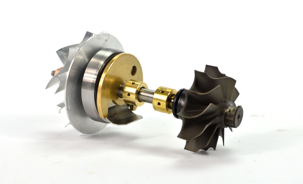
Example of a center housing & rotating assembly (CHRA) for short
Looking at the image above you can see the CHRA of the Honda Civic Turbocharger. On the left side we have the compressor wheel and the right side is the turbine wheel. You’ll notice that the compressor wheel exducer (the larger diameter of the wheel) is larger than the turbine wheel inducer (also the larger diameter of the wheel).
This wheel diameter ratio has a lot to do with the boost control, response, power capacity and bearing wear, so it is important to consider this when designing a performance turbocharger.
A high value ratio (aka too large of compressor wheel) can cause adverse effects on the turbochargers overall performance and reliability.

OEM compressor wheel
The compressor wheel found in the Honda Civic Base Models, SI, and CRV all share the same dimensions with a 39.1mm inducer and 46mm exducer; this creates a very large trim wheel at 72.3. Trim is the ratio of the exducer and inducer diameters and has effects on the peak pressure ratio and boost response characteristics. For reference, a larger performance turbocharger compressor wheel typically has a 50-60 trim wheel.

OEM turbine wheel
Now this is where it gets a bit more interesting with the OE turbochargers.
The image shown above is found on the base model Civic EX, LX, and Sports vs the Civic SI and CRV which have a different turbine wheel design. Both turbine wheels share the same 37mm inducer diameter (the larger side), but the SI and CRV have a 1mm larger exducer (the smaller side) diameter at 33.5mm. Not only is there a dimensional change but the number of blades and the profile of the blades between the two wheels are different. This difference in blade profile and count (11 vs 9) is why the SI/CRV turbo outshines the base model in performance. We will expand on the details of wheel design later in our next turbo design blog.
The bearing system of a journal bearing turbocharger
Lastly is a quick peak into the bearing system of a journal bearing turbocharger. Much like the crankshaft of a modern internal combustion engine, a journal bearing turbocharger depends on a very thin dynamic fluid barrier between the turbine shaft and the bearing for lubrication and radial shaft control; these are the two small “rings” in the image above. The larger “disk” is the thrust bearing which also depends on a fluid barrier for axial shaft control. Journal bearing systems are extremely simple and typically very reliable as longs as proper lubrication is applied and a well-designed wheel size ratio is used.
So, we’ve thrown a lot of big terms around in this blog and only skimmed the surface of how a turbocharger functions.
We plan to really dissect a performance turbocharger as we dig into the design of the soon to come 27WON W1 Turbo in the next blog coming out on March 31st. In the meantime enjoy this video of the Fastest ¼ Mile CivicX equipped with the 27WON W1 Turbo.
Thanks for tuning in with 27WON Performance.
I dare you to REDEFINE!
-Barett @ 27WON